We have all heard the phrase “work smarter not harder”. So, why when you walk through the shop floor do you still see set up people and machinists tapping on the side of a cutting tool in the machine spindle with a tiny brass hammer like little cobblers trying to get the TIR dialed in?
To quote Chuck Miller from "Fine Homebuilding": “There’s a better way”.
 Before we tell you the better way, let's discuss TIR. What is it? Where does it come from? Why is it bad? How do we fix it?
What is it? TIR stands for Total Indicated (or indicator) Runout, which is a measurement of the amount of displacement of the tool shank relative to the spindle centerline.
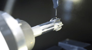
Where does it come from? The two most common places are from the machine spindle itself or from the tool assembly. The least likely place is from the spindle. To measure the spindle runout, place the tip of an indicator on the inside taper of the spindle and slowly turn the spindle by hand. The indicator should have a read-out in tenths or microns since there should be very, very little runout (hopefully). If there are more than a few tenths, then it might be time for a spindle rebuild or replacement as it is nearly impossible to adjust or fix this runout.
How to measure TIR
Why do tool assemblies have the greater amount of runout? Part of it comes from the assembly process and part is determined by the tool holder design. It should go without saying, but the components that need to be assembled should be free of oil, free of chips or swarf, free of damage for optimum performance. See below for differences in tool holder design TIR performance.
Runout by holder design:
- DA collet system – 0.001” at face of collet
- TG collet system – 0.0008” @ 2” (50 mm)
- ER collet system – 0.0005” @ 2” (50 mm)
- H/S Shrink system – 0.0001” @ 2” (50 mm)
- Hydraulic system - 0.0001” @ 2” (50 mm)
Why is TIR bad? Large amounts of runout will reduce tool life, create poor bore finishes, and produce oversized holes. There may also be vibration issues from out of balance high RPM tools which will make things even worse.
How to mitigate TIR
How do we fix or reduce TIR? For collet systems, there are a few ways:
- Tap on the tool shank with a hammer. Tedious, time consuming, and not accurate. Plus, it only will work on tools with a steel shank. Rap a solid carbide tool, and you have a tool with zero life left.
- Use a “high precision” collet. Be sure to use a torque wrench for proper tightening. This will be better than a standard collet since the collets are sized to the exact tool shank with very little collapse.
- Use a special compensation nut with set screws to move or push the collet in a radial direction, similar to adjusting a four jaw chuck. Monaghan Tooling Group has these easyZERO Nuts in various sizes: ER16, ER20, ER25, ER32, & ER40. They use a standard ER collet and can correct for just about 0.002” (0.050 mm) of TIR. Using the set screws allows a very precise amount of movement. This system is quick and clean with no hammers required.
For a hydraulic chuck system, there is a similar set up available. The hydraulic chuck is mounted to a compensation adapter to fit the machine tool spindle. This system uses four screws to push the chuck in a radial direction to eliminate TIR (similar to the EZ-Zero Nut). The nice thing about this system is that once the chuck has been dialed in, the TIR will stay the same during tool change overs - provided the assembly stays with that same machine (be sure to check it!).
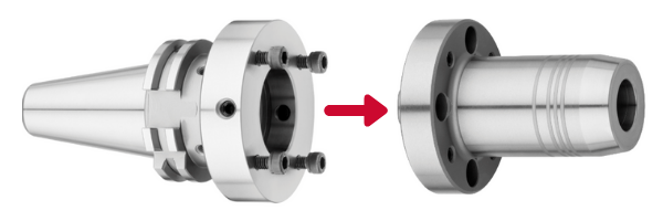
This system also allows adjustment in the axial direction as well, which is important for tools with multiple diameters so all diameters run true. Besides mounting hydraulic chucks to the compensation adapter, the system can be used with flange holders to fit reamer rings from Ø1.968” (Ø50 mm) up to Ø7.874” (Ø200 mm).
With all of this technology available, there is no reason to keep hammering at your tool or your head against the wall. Use compensation adapters…. because accuracy matters.